Friday, 12 April 2024

Oddest ball magic trick circuit


 Our circuit is relatively simple.
https://crcit.net/c/0a3500cf57c84414afd53d279ac5571b

There's an LDR connected to the "lower half" of a voltage divider, the middle of which is connected to an "analogue" input pin (ADC) on the Arduino Pro Mini.
With no light on the LDR, the resistance of the LDR will be pretty low, and the input value on pin A0 will be low. As more light hits the LDR, the resistance increases (ensuring more of the supply voltage gets to the input pin) and the "analogue" value read by A0 increases.

When the LDR receives enough light that the input value exceeds some threshold value, we will activate the buzzer (light the LED and trigger the base pin of the transistor) and also send a (one-shot) message to a serial/UART bluetooth module.
The base pin of the transistor (connected to the siren) is pulled low through a 100K resistor - this ensures that when no signal is applied from output pin D9, the siren will not sound.

To set the threshold value (sensitivity) we have a potentiometer connected to the analogue pin A1.
This allows us to change the amount of light at which the "triggered" state is entered.

The switch connected to D8 input pin is simply a "debug" pin - if set, we'll send a continuous stream of value readings out over the serial port, to help with any debug/setting up. If the debug option is not set, we won't be "spamming" the serial port with a continuous stream of data.


int led_pin = 13;

int ldr_pin = A0;

int sensitivity = A1;

int ldr_value = 0;

int debug_pin = 8;

int siren_pin = 9;


int threshold_value = 100; // this is read from the sensitity pin

int state = 0;

int prev_state = 0;

int in_debug = 0;


void setup() {

  // put your setup code here, to run once:

  pinMode(led_pin, OUTPUT);

  pinMode(ldr_pin, INPUT);

  pinMode(sensitivity, INPUT);

  pinMode(debug_pin, INPUT_PULLUP);

  pinMode(siren_pin, OUTPUT);


  digitalWrite(siren_pin, LOW);

  digitalWrite(led_pin, LOW);


  Serial.begin(9600);

  Serial.println("Let's go!");

}


void loop() {


  if(digitalRead(debug_pin) == LOW) { 

    in_debug = 1;

  } else {

    in_debug = 0;

  }


  threshold_value = analogRead(sensitivity);    

  ldr_value = analogRead(ldr_pin);

  if(in_debug == 1) { 

    Serial.println(ldr_value);

  }


  // if we've exceeded the threshold,

  if(ldr_value > threshold_value) {     

    state = 1;    

  } else { 

    state = 0;

  }  


  if(state == 0) { 

    digitalWrite(led_pin, LOW); 

    digitalWrite(siren_pin, LOW); 

    if(prev_state != 0) { 

      // send a reset message to the bluetooth device

      Serial.println("Reset");  

    }

  } else { 

    digitalWrite(led_pin, HIGH);

    digitalWrite(siren_pin, HIGH);

    if(prev_state == 0) { 

      // send a one-shot message to the bluetooth device

      Serial.println("Active");

    }

  }

  prev_state = state;


  delay(100);


  // if we're in debug mode, increase the delay between loops

  // (makes it less responsive, but avoids spamming the receiver

  //  with loads of noise)

  if(in_debug == 1) { 

    delay(400);

  }


}


Now we can simply connect a HM-10 bluetooth module to the serial pins, and have our device "talk" to a connected smart device, like a phone or tablet

Thursday, 11 April 2024

Oddest Ball magic trick

 Having only seen the Oddest Ball magic trick in action, we're not 100% sure of what goes into it. But it's relatively simple to take a guess, and make something similar (even if it's not an exact copy).

But the basic idea is to have a long, thin "box" into which we'll have some holes, into each of which we place a golf ball (or similar-sized ball). Underneath one of the holes, we'll have a light-dependent resistor (LDR) and use this to detect whether the ball is present in the hole above.


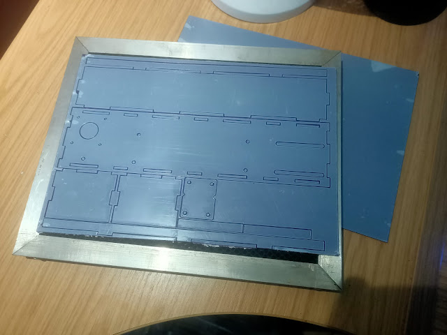
Creating the box is relatively straight-forward: drop the design (above) onto the laser cutter and carve it out of 3mm mdf.

then quickly assemble the box and glue together using PVA glue


Some masking tape along the edges holds everything in place, while the glue dries.
Now, below the hole that will contain our red ball, we glue a small "drum" with a hole for an LDR (light dependent resistor) in the base. The idea is that when the ball is in place on top of the box, it will block all light from reaching the LDR.

When the ball is picked up, light will flood into the drum, and cause the resistance of the LDR to increase. We'll be able to detect this change in light level, using a voltage divider to create a variable "analogue" signal into a pin of a microcontroller.

When the LDR changes and we can detect that the ball has been lifted off the base, we'll generate a signal (and maybe trigger a siren or buzzer or similar alarm on the device itself).

Wednesday, 3 April 2024

And now for something completely different

 Just as our previous Nerd Club blog would often jump around between topics and ideas, so - it seems - this one is destined to do the same!

You see, we're still working on our Full Title electronic jousting game.
We've got some re-scaled minis (80% of full-scale from Highland Miniatures) that look much better on our jousting arena, and some different sized complete-loop timing belts (840mm and 920mm) which help improve the look and feel of things.

But the butterfly mind strikes again. And we're focussed on something completely different! (but a much simpler, smaller, self-contained project). 

For many years, a few of us have been attending the Blue Sky Music Open Mic nights, in and around Worthing. They're run by a smashing guy called Beany (and his wife Beth) and they're fantastic fun. And it's a true open-mic; not just singing, but performing, spoken word, poetry and even.... magic.

I always fancied having a go at performing some magic and have been watching a few performances from comedy magician Craig Petty. I really like his style, and love the way he goes into great depth with not just his tricks, but his performance advice too. When I invite others up to play when it's my turn to play a few songs, most open-mic jam sessions end up slightly chaotic, but we all have a bit of a laugh. So I thought I'd try something similar with a magic routine.

This one - called "Oddest Ball" - looks like a great "opener"

I love the comedy effect - and everyone immediately "gets" the gag. The only downside is that at over a hundred quid for a one-off laugh, it's a bit pricey! (I know that professional magicians "price in" how many times they get to use a prop and may come to a different conclusion).

But the hardware behind this seems pretty simple. And there's probably even a way we could improve of this - as well as produce it for a fraction of the £100+ price tag. I'm thinking of even having some kind of bluetooth-aware app running for the performance - so use the app to play some spooky "magic music" though the same P.A. system running the walk-around microphones. Then, when the appropriate ball is lifted, have the app play a loud siren/klaxon sound through the P.A. (rather than have to provide and power a built-in klaxon device).

In truth, we'll probably incorporate both.
But that's the basic idea - some hardware that can detect when a ball is lifted from above a sensor (LDR immediately springs to mind) that then triggers a super-loud klaxon sound. Nice and simple......

.... now where did I put those Arduino Mini boards that have been hanging around for the last five years or so...?

Tuesday, 12 March 2024

It's not just our track that needs resizing

 Highland Miniatures create some beautiful looking Mounted Questing Knights 
https://www.myminifactory.com/users/Highlandsminis


The horses have plenty of decoration for painting different types of heraldry and the knights look nice and easy to paint (I'm thinking black, drybrushed silver, edge highlights in bright silver and a few little spot details would be enough to call them done!).

I hollowed and printed a couple of knights to try thing out.
My default process for printing pretty much any miniature is to take the Ryan Ford character from Titan Forge (before they created their sci-fi spin-off division, Cyber Forge) and scale everything to him.
I find the Cyber Forge miniatures to be just the right size for me - small enough to still qualify as 32mm "heroic" but large enough to be able to paint tiny details like eyes and facial details.

So I scaled these knights to match my preferred scale and set them running around the jousting track


Disaster!
While the horses travel the track just how we want them to (facing the right way, turning around the bar at the end of each run etc) just watching the whole performance makes it look like the bar is only about five feet wide!

One of the constraints we're having to work with, is the size of the closed-loop belt we're using (we tried making our own belt and it failed under tension) and the largest size belt I've got it 610mm. We might be able to go a little bit bigger - but the other constraint we have is the size of the laser cutter we're using (which can only take sheet materials up to about 300m wide).

So even if we had a larger belt, we're not able to cut a large base for it to run along (without making our playing surface out of multiple sections and joining them together). So the obvious thing is to try to make our miniatures.... well.... more miniature.
We'll try scaling our minis down in 10% increments until we find a size we're happy with.
Anything smaller than 80% or so, and we'll just have to give up on trying to paint eyes and any similar tiny little details - but that might be no bad thing either; we can just stick to knights with full-face, closed helmets!

Monday, 11 March 2024

The iterative process (again)

 When we first designed our "race track" for the jousting knights to move around, we picked the dimensions of a typical GW horse base as being 60mm x 35mm


This requires the distance between the horizontal arms of our track to be at least 35mm apart (assuming the knights will travel perfectly along the centre of the track. Since we need half-a-base-width for each knight, and there are two knights, it was easy enough to arrive at 35mm distance apart.

We then allowed 6mm for our "bar" between the two knights (the bar to be cut from 3mm mdf plus a few mm for any embellishments) and we quickly arrived at a minimum distance of not less than 42mm apart.

But that was assuming that the drive belt would be running through the middle of our character bases. But since we mounted the magnets on little "arms", that's no longer the case. And watching our two fake-bases travelling around the track (see previous video) they do appear to be quite a way apart from each other.
Our knights are going to have to carry extra-long lances, just to reach each other, over the bar!

So I guess we're going to have to redesign the size/shape of our track, to make it "thinner" and have the horses run past each other at a closer distance....

Saturday, 9 March 2024

Making a complete circuit

 It may not be obvious in the earlier video (our first successful test, driving two magnets across the top of a playing surface) but one of the magnets spins quite a lot, as it is dragged along by the magnet underneath (the one that is fixed to the belt).

Clearly, we don't want our knights to be spinning around like the teacups ride at a travelling funfair - we want them to face the direction they are travelling in!

So we added a second magnet, just behind each existing magnet on the belt.

The idea is that our knight miniatures will have not one, but two, magnets in their bases. To ensure our knights miniatures are placed facing the correct direction on the board, we reversed the polarity of the rear-most magnets (so if you try to place your knight facing the wrong way around, instead of attracting to the belt, the magnets in the base will repel each other, and it will be clear that the knight has not been placed correctly on the playing surface).

So now we were ready to actually try the whole thing out - to get our knights to complete one (or more) complete circuits of the track (and hopefully keep facing the right way around, throughout!).

It'll be interesting to see how two magnets a set fixed width apart (on the miniature base) work with the magnets underneath that might change the distance between them (as they travel around curves/corners on the track). I guess there's only one way to find out - build it and give it a go!

Yay! Looking very promising!

Thursday, 7 March 2024

Finally making some progress!

 So having just a single thin sheet of acrylic to support our stepper motor and drive belt isn't good enough, and we need to add some braces to the acrylic to stop it from deflecting when the belt is under tension.
What we need is some "sides" on our stepper not-yet-an-enclosure.

We had some A4 sheets of 3mm acrylic knocking around (it's been hanging about for years) so threw together some designs in Inkscape and set the old laser cutter going again


Talk about cutting it fine! We just about got everything cut from a single sheet of A4. (ok, everything bar one side piece - but we managed to squeeze an awful lot onto a single A4 sheet!
We assembled the box shape and fitted the stepper motor inside


At the other end (and mostly because we couldn't be certain of exact dimensions when first designing our race track, before the continuous loop belts had arrived) we fitted the two bearings to a sliding "carriage".
The carriage is fitted to the "box lid" through two long slots (and some more tapped and threaded holes directly in the acrylic carriage material). This way we can wrap the belt around the bearings and the pulley on the stepper motor, then slide the far bearings away from the motor, adding more (or less) tension to the belt, as required.


With everything installed and the bearings set to the correct distance, we gave our belt a quick test, to make sure it could rotate around the bearings freely. Everything was working well. The plastic no longer had any flex in it, the belt was perfectly horizontal, and no matter how many times we span it around and around, the belt never once tried to work itself up and over the tops of the bearings.

Now we needed to find a way to fix some magnets to the belt in such a way that they could move freely, in close contact with the "lid" (yet to be fitted) but without them getting snagged or tangled up with the bearings/pulley.

We couldn't clip anything over the belt (since it would eventually run over the bearings or get snagged in the pulley on the stepper motor). But - as currently set up - nothing ever comes into contact with the outside face of the belt.
We figured we could glue some little "brackets" to the outside face of the belt, and add our magnets to these. A little bit of bent solid-core wire was just the job!


Superglue on drive belts isn't a brilliant idea - we've already had experience of it failing, when we made our own belt-loop, made by super-gluing the end edges of a single length of T2.5 belt together, then reinforcing with some plastic, superglued across the join.

The problem with superglue is that it makes a "stiff" section in the belt.
But our solid core wire is barely 1mm thick. So the amount of surface area affected by the superglue will be very small.
Once we'd got our "wire brackets" fixed to opposite corners of the belt, we superglued a 5mm disc neodymium magnet onto each one (making sure to use similar polarities for ease of use later). With the magnets fixed to opposite corners of the belt, rotating it caused the two magnets to appear to travel towards each other, until they passed each other, somewhere near the middle of the track.


After a dry-run, pushing the belt by hand, it was time to run the motor, and made sure that the magnets could travel freely and easily around the outside edges of the bearings

Everything looks like it's going to plan. Just one last test to try out - the big one. The one that will tell us whether this entire project will even work or not!
The idea is to place two knights on horseback on top of this belt - each knight having a magnet in his base. As the belt spins, under the playing surface, so the magnets with travel around the outside of the circuit, described by the belt. And if our tabletop miniatures also have magnets in them (presuming we've fitted them with the correct polarity) then we should be able to get our knights to travel towards each other (for each round of the jousting competition) then away to tournee around the rail and prepare for their next charge.

The big question is - as a concept, would these even work?

And here's the final result.
A playing surface, on which two magnets appear to travel, completely without restrictiom.
It looks like we might be on to something after all....